


Warning
I cannot be held liable for any use/misuse of this information, the resulting design / assembly / operation / maintenance / etc are all strictly your own doing. This is a dangerous machine and my plans were thrown together on the spot from sources gleaned on the internet and through the actual assembly process – the actual circuit diagrams were drawn up after the machine was built for the purpose of this tutorial and may not even reflect the actual circuit – though I’ll try to keep it simple and straightforward – use common sense: if you don’t know what your doing don’t do it – in fact the only thing you should even be here for is the Arduino/C#.net code (bottom of the article)- which I also cannot be held liable for.
Introduction
I began some experiments requiring custom vacuum tubes a couple months ago, and after checking into the costs of having them made – decided to make them myself. I will be posting tutorials as I complete various aspects of this project that may be of use to others – for now here’s one for how to make an Arduino/C#.net powered precision spot welder with 1, 2, 3 and 4 Amp (easily modified for your purpose, but I’m using this for pretty small parts) power settings and millisecond-precision timing.
Sources
I used these two write-ups online as a reference when building my spot-welder:
http://users.frii.com/katana/spotweld.html
http://www.5bears.com/welder.htm
Power Source
I put together 2 power sources for this project, one is 12VDC/350mA and the other is appoximately 4VAC/360A – a bit of overkill but it will be easy to expand later if I need to.
12VDC/350mA Power Supply
I just went to radioshack and picked up a 120VAC/12VAC transformer, rectifier, capacitor (pretty large for safety’s sake since I’m running the 350mA and 360A sources off the same cable which might induce some heavy ripple when it fires), and 12V regulator – in actuality I should have gone with the 12.6VAC transformer because the 12V regulator drops the voltage to 11.9V – not terrible, but it irritates me enough to regret not getting the 12.6V transformer.
4VAC/360A Power Supply
This power supply was a bit harder – the first thing was finding a transformer with secondary windings that could be stripped off – even with the internet its no easy task, but I ultimately found a 120VAC/120VAC/12A isolation transformer at a surplus depot online – I would highly recommend searching for an isolation transformer if your doing a project requiring a transformer of this type as it will save you a lot of frustration trying to determine whether the primary or secondary is on the outside from what are often bad photos – you can’t really go wrong if their both the same to start. I pulled the secondary windings off the coil with pliers, blood and cursing and then wrapped some 4-gauge wire acquired from amazon.com around as a new secondary until the voltage readout was approximately 4VAC (be careful and use the proper equipment measuring this – its 360 amperes minus 5-15% for transformer losses – enough to kill you several times over). It is worth noting here (as I will mentioning it below, multiple times can’t hurt): power is controlled to this transformer via a solid-state relay on the 120VAC side – it is kept unpowered while not in cycle for safety reasons though should still be treated cautiously as my design does keep 1 wire hot – I might add a second solid-state relay later to alleviate this hazard. A suitably sized isolation transformer costs about $100 and is by far the most expensive component of this project.
Control Circuitry
The vast majority of the circuitry is for controlling the various power settings, the foot switch, the warning light and the actual firing relays.  Relays are done in 2 stages everywhere for paranoia’s sake (isolation) and because my design revolved around a 5V controller board (an Arduino Duemilanove with blue back-lite LCD shield I had laying around) and a 12V supply – plus most solid state relays that can handle high enough power levels are run off 12V or more, not 5V).  Circuit diagram and parts list follow to simplify the explaination:
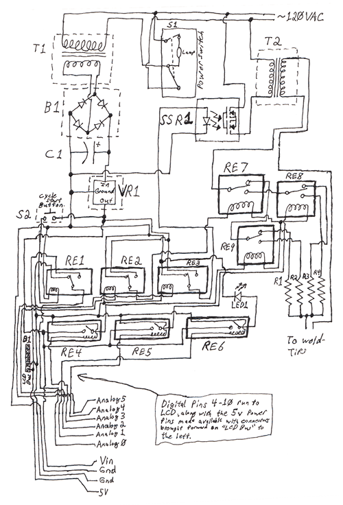
B1(top): Bridge Rectifier
B2(bottom): Bus to allow Arduino LCDShield to get 5V power from the Arduino Board with this circuit connected to it directly
C1: 4700uF Capacitor – This is likely overkill, you just need something to smooth the voltage out and help absorb the spikes when SSR1 fires.
LED1: 12V warning LED – comes on as cycle starts until the cycle is complete
R1: Custom NiChrome-wire-wound resistor on cermaic pole – 1Ohm
R2: Custom NiChrome-wire-wound resistor on ceramic pole – 2Ohm
R3: Custom NiChrome-wire-wound resistor on ceramic pole – 3Ohm
R4: Custom NiChrome-wire-wound resistor on cermaic pole – 4Ohm
RE1: 12V SPDT Relay – connected to S2 as the mechanism to start a cycle, feeds +-5V into Arduino pin A0
RE2: 5V SPDT Relay – feeds +-12V into RE7 for power selection (levels 12/34) connected to Arduino pin A2
RE3: 5V SPDT Relay – feeds +-12V into SSR1 for cycle start/stop connected to Arduino pin A5
RE4: 5V Reed Relay – feeds +12V into RE9 for power selection (levels 1/2) connected to Arduino pin A3
RE5: 5V Reed Relay – feeds +12V into RE8 for power selection (levels 3/4) connected to Arduino pin A4
RE6: 5V Reed Relay – feeds +12V into LED1 as the cycle is about to begin until it has completed to power the warning LED
RE7: 12V 40A SPDT Relay – switches current from T2 though to the next level of power selecting relays (RE9/RE8)
RE8: 12V 40A SPDT Relay – switches current for power levels 3 and 4
RE9: 12V 40A SPDT Relay – switches current for power levels 1 and 2
S1: Primary power switch – self-illuminated 120VAC 3 pole switch from RadioShack
S2: Momentary pushbutton cycle start button – I’m using a tattoo gun foot pedal
SSR1: 220V 40A solid-state-relay – controls the power to T2’s primary coil
T1: 120V/12V 350mA transformer from RadioShack – I’d suggest going with the 12.6V to compensate for VR1’s 0.1V drop
T2: 120V/120V 12A isolation transformer with secondary replaced with a enough turns of 4-gauge wire to achieve 4VAC (BE CAREFUL MEASURING!!!)
VR1: 12V voltage regulator from RadioShack
After typing this up I’ve noticed I actually did wire my resistors (R1-R4) backwards, so my power levels are highest-lowest 1-4, while this irritates me slightly, they were far to difficult to mount to the relays (being in the range of 1-3 inches long and a quarter inch around each) to bother changing it, I’ll have to remember that 4A is level 1, 2A is level 2, 1.3A is level 3 and 1A is level 4 – I’d suggest correcting this if you implement various power levels – the software will work the same for 4 settings and I might end up changing resistors out later on if required
It is worth noting that since the initial design of this circuit I have removed the 4 power-limiting resistors as they were too large at 1-4 Ohms. I might put these back in lower resistance forms later on, but I’m getting good results just using the amount of time as a limiting factor so I’ll probably leave them out. The whole resistance-limiting portion + control circuitry is definitely more hassle than its worth as limiting the duration down to milliseconds with an Arduino works great and I wouldn’t recommend you bother with them if building this from scratch (components RE2, RE4, RE5, RE7, RE8, RE9 R1, R2, R3, and R4 are strictly for this purpose).
I have also added a second solid state relay not shown in the diagram to satiate my own paranoia of having a live wire. The second SSR has the control wired in parallel to SSR1 with the output feeding through the line of T2 connected directly to the mains line in the diagram above.
When connecting the Arduino to the LCD shield be careful to get the polarity right on the power connectors. Sadly, when I got close to testing I over-anxiously assembled the quick-connects and whatnot inside the project box, reversed the polarity on the LCD shield power cables and burnt out the very cool looking blue back-light. The LCD still works, but requires ambient light and the entire thing emits nothing but red light from various LEDs in the power switch, warning lamp, and 2 SSR’s – it just feels like something made in the 80’s without blue.
Further Commentary
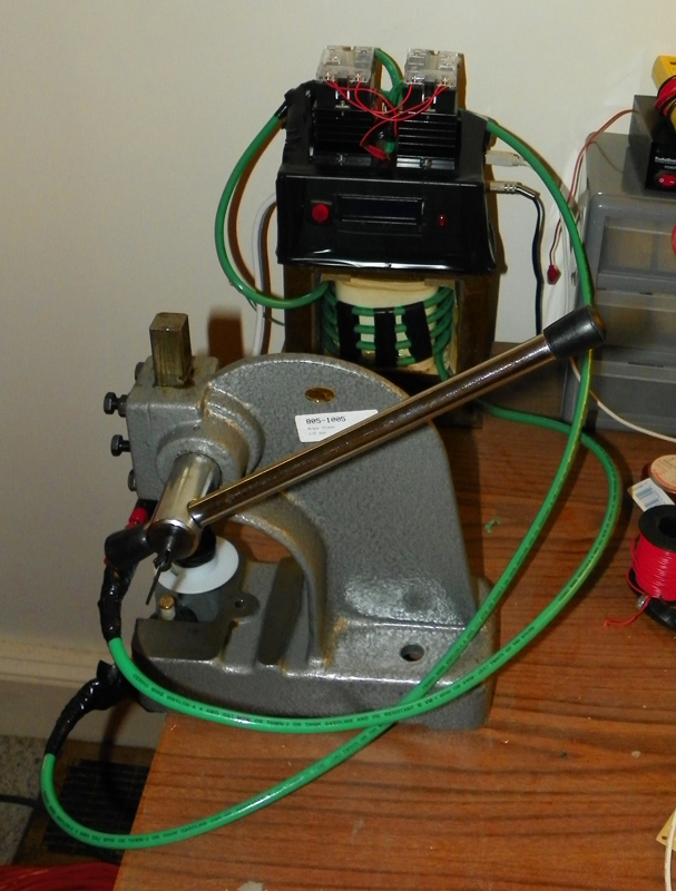
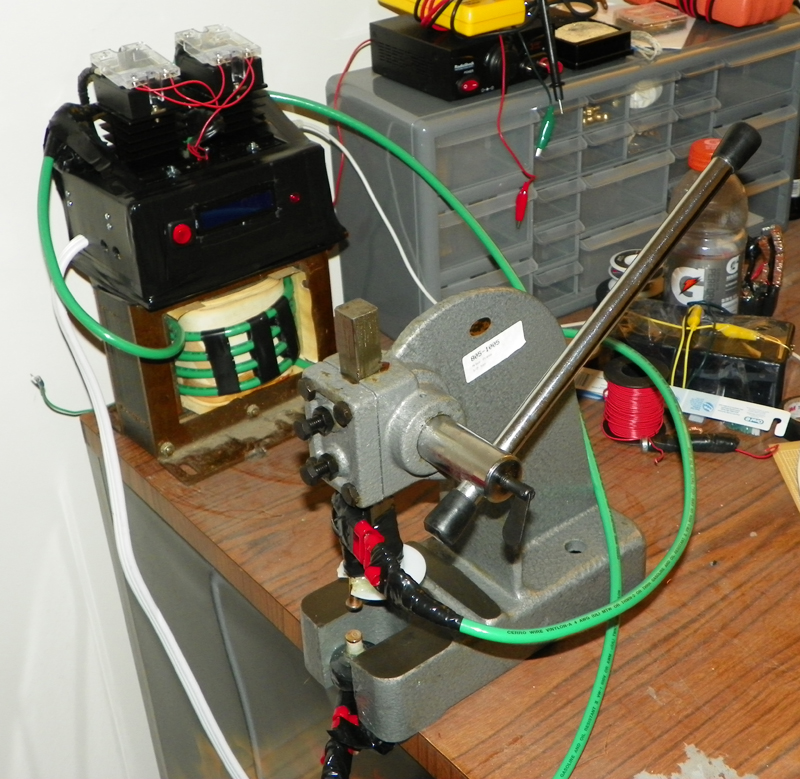
I used a 1/2 ton arbor press for the body of it (obviously not used as a press for pressure) with some PVC mounting tubes holding some large 1/4″ diameter brass hinge pins from home depot as the electrodes, banana connectors on the wires to the circuitry and lots of electrical tape and epoxy for insulation from/support onto the arbor press.
If you want to make the new secondary on the transformer look decently and not have too much loss I would recommend using spacers between the individual turns – I used 3 pieces of 1/4″ plastic tube (a shipping container for pre-straitened NiTi wire from Amazon.com) between each turn on each side – held in place with the electrical tape you can see in the photos above. The cables coming out in the photos at the top of this article are: white power cable on left, green welding wires, white USB cable and silver/black tattoo gun foot pedal on the right.
Code
This may be a bit buggy as I haven’t tested it extensively – it does experience a couple different types of glitches when disconnected from the computer at different times, though I only intend to disconnect it from a computer when I’m done using the spot welder so this isn’t an issue for me and probably won’t be fixed.
Here is the sketch for the Arduino (just requires selecting the correct board from the Arduino sketch editor and uploading to board):
And the C#.net code for storing and loading of cycles on a computer via USB: